
 P0k3sm0t
SEE WHAT THE TOOL MAKES
Try a studio sample
These previews show the actual downloadable models. They are geometry renders, not photographs of physical prints. Each kit includes print notes; choose your own printer and filament before slicing.
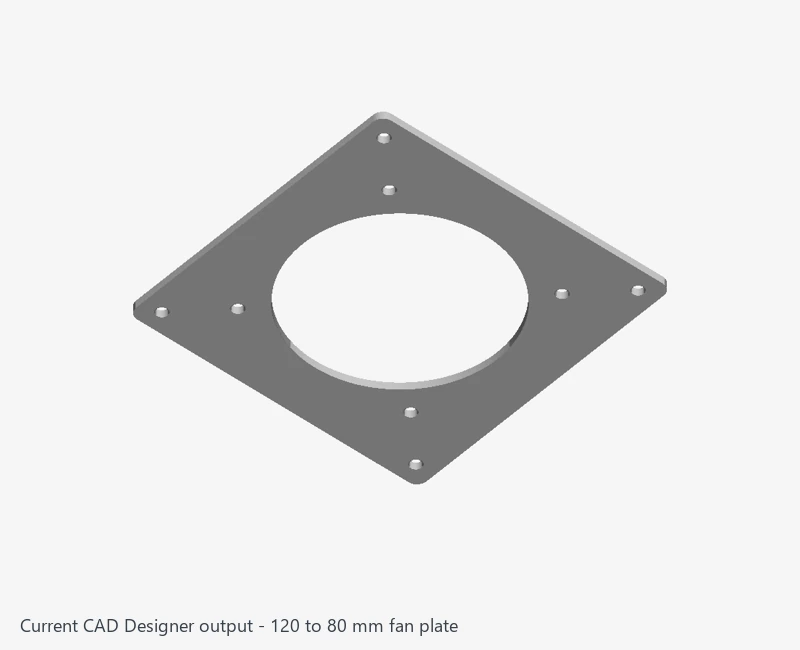
Fan adapter slicing practice
Use this flat adapter to practice importing, choosing your own presets, slicing and inspecting layers.
About this sample
Refreshed from the included reviewed feature specification with the current CAD Designer builder on October 27, 2026. Use Recreate this sample for the form settings. Print flat and check both mounting patterns before use. This is a flat adapter plate.
Slicer Studio lets you prepare a model in your browser and slice it with the same OrcaSlicer engine used by Homebrew Printing.
QUICK START
1. Select Add model or drag an STL, 3MF, or OBJ file onto the build plate. Confirm the source units and check the object list for multipart imports.
2. Work through Printer, Filament, Print settings, then Review. Choose the actual printer, nozzle, build plate and filament; review imported process settings before slicing.
3. Select an object to move, rotate, resize, duplicate, arrange, measure, or lay a face on the build plate.
4. Select Slice plate.
5. Review the actual sliced layers, tool assignments and warnings. Save the editable project or export 3MF when needed, then download the verified G-code. Changes to geometry, print settings or layer pauses require another slice.
Projects and saved profiles are available when you sign in. A guest can prepare and slice a temporary project, but guest settings are not saved.
PRINT SETUP WORKFLOW
Work through Printer, Filament, Print settings, then Review. Printer contains build surface and multicolor hardware; bed temperatures follow Filament. Filament contains materials/colors, manual layer changes and color mixing. Review shows progress, estimates, filenames and downloads. Project actions and Preset actions group saved work. Search spans all steps. Tabs/search keep completed slices available.
CURRENT WORKSPACE AND SAVED SETTINGS
If workspace loading fails, use Retry loading. Selected files and the project name stay on this page; retry refreshes the connection without reloading the page.
FILE IMPORT AND MODEL HEALTH
Add model accepts STL, 3MF or OBJ up to 90 MB, 5,000,000 triangles and 6,000,000 vertices. A 3MF may expand to 400 MB with 200 entries. Expansion and encryption errors are distinct. Encrypted entries, external component URLs and unsafe archive paths are rejected.
3MF IMPORT CHOICES
A 3MF may include print profiles or only geometry/colors.
Load 3MF settings: use your saved project or a trusted setup for the same printer/nozzle. Loads supported printer, process, filament and color settings, replacing current values.
Use file colors only: choose this to keep YOUR current printer, nozzle, process and filament presets while importing the model’s colors. Temperatures, layer height, speeds, acceleration, supports and other print values stay unchanged. Only the palette and color assignments are imported; file profiles and object print overrides are ignored. Saved presets are not overwritten.
Example: for a colored Snapmaker 3MF on your configured Prusa XL, choose Use file colors only. For files with colors but no profiles, the button is Use file colors. Configure enough filament tools and review mappings; the option explains when more tools are needed.
Keep current settings: use a model made for another printer, or keep your tuned setup. Adds geometry using your current printer, process, filaments, colors and custom values. Embedded settings/color assignments are cleared for this import; the original file is unchanged.
Send to Support Fin transfers the selected part with its current print colors and paint. The plate stays open on the website. Returned 3MFs include the part and fins. Load 3MF settings disables automatic supports; otherwise switch them off and match the fin layer height (sample: 0.20 mm).
Review printer/nozzle, materials, settings and tool assignments, then slice and inspect Preview. Save project to retain the chosen setup.
Read Model check after import. Common defects are repaired in a private copy before slicing; originals and intended size are retained, with repaired output in millimeters. Repair mesh is also available. Unresolved openings need CAD/mesh repair and re-export. Simplify mesh reduces detail: retain the original and recheck holes, shape and paint.
SELECTION, CAMERA, ROTATION, AND HISTORY
Left drag rotates the view; right drag pans. Pan Off / Pan On switches left dragging to panning. Reset view recenters the camera without resetting the model. The bottom-left view cube shows the camera orientation; select a face for a standard view. Its nearby controls provide the default 3D view, View menu, and Fit model. The colored X/Y/Z axes identify build directions. The build plate becomes translucent when viewed from underneath so the model bottom remains visible.
The selected printer's bed and artwork appear when available; custom printers use their configured dimensions. The handle and physical rim are not printable space. The number identifies the active plate.
Right-side quick buttons: Clear active plate (with confirmation), Auto orient selected model, Arrange active plate, Lock view rotation, Print settings, Top view, and Reset view. Hover/focus for names; Up/Down moves focus. The lock prevents orbit dragging while allowing pan and zoom; click again to unlock. Print settings opens Quality. TOP also opens the overhead view. Camera controls preserve the model and completed slice. Both the right-side quick buttons and the bottom-left camera controls can be collapsed and restored; each device remembers its choice.
The model toolbar uses labeled outline icons on desktop and phones. Hover or keyboard focus shows one tooltip. Left/Right, Home, and End move focus between enabled tools. Escape closes a menu. Dimmed model actions require a selected model or an available history step.
Add plate is beside the plate tabs. Select, Move, Rotate, Resize, and Lay on face are grouped together, followed by Orient, Arrange, and Repair. Paint, Text, and Cut have direct controls. Tools groups Object actions (including Duplicate, Measure, Rename, Remove, Clear plate, and Reset object), Modify model (Split parts, Simplify mesh, Boolean tools, Brim ears, Layer height, and Modifiers), and Organize plates (assembly, instances, plate transfers, and Support Fin Studio). Undo/Redo are beside View. View holds Pan and Reset view; the separate Calibrate button beside View opens the available calibration tests. Reset object changes a model transform; Reset view changes only the camera.
Select all selects every object on the active plate. Ctrl-click or Command-click objects in the list toggles individual selection. Clear plate removes every model from the active plate after confirmation and leaves other plates unchanged.
Move, Rotate, and Resize handles appear at the selected part instead of the file's original origin. Move has red X, green Y, and blue Z arrows; drag blue Z to raise or lower the part. The Move card provides X/Y/Z position values, World or Plate coordinates, alignment actions, and Drop to bed. Read the selected coordinate system before entering values: World uses the plate center for X/Y, while Plate uses its front-left corner. Position uses the part center; Drop to bed places the actual lowest point on the bed. Moving a part below or outside the build volume shows a warning.
Lay on face: choose the tool to show selectable surface patches, hover to highlight a candidate, then click or tap the surface that should face downward. The part rotates in place and its actual lowest mesh vertices are placed on the bed. It also works after raising a part with Move Z. Inspect recessed or internal faces carefully: other features may extend below the selected surface. Move, Rotate, Resize, and Lay on face can be undone with Undo.
Rotate shows degree markings around the rotation rings. Snap offers Off, 1, 5, 10, 15, 30, 45, or 90 degrees, with 5 degrees selected initially. Snapping rotates objects, not the camera. While dragging a rotation ring, moving over a degree tick snaps to that tick. The Rotate card also provides relative and absolute X/Y/Z degrees. Resize provides scale percentages and dimensions, with a uniform-scale option. Cut opens its own card with axis/position, keep/place/flip choices for each side, and optional alignment pins; inspect the result before exporting.
Undo and Redo restore moves, rotations, and resizing. Use Ctrl/Command-Z, Ctrl/Command-Shift-Z, or Ctrl/Command-Y when a settings input is not focused. This is transform history, not a promise that every deletion or mesh edit can be undone. G, R, and S select Move, Rotate, and Resize outside text inputs.
Possible overlap compares bounding boxes; curved or interlocking parts can have intersecting boxes without intersecting surfaces. This warning does not block slicing. Inspect the actual mesh and toolpaths; overlapping copies can still intersect genuinely.
PRINTER, FILAMENT, AND PROCESS PROFILES
Common printer and Custom printer are buttons below Simple / Advanced. Choose the real printer and nozzle first. Add custom printer can inherit an installed Orca preset or use None · fully custom. None saves independent dimensions and limits; the verified Orca engine baseline is still used when needed during slicing. Review its scripts for your firmware rather than assuming blank fields send no commands.
Upload OrcaSlicer profile accepts machine JSON or .orca_printer/.orcs bundles. Bundles load all included process and filament presets, resolving bundled or installed system parents. Use for this session adds temporary presets; Save keeps them all in your account, linking filaments to the printer. Review dimensions, nozzle, limits, scripts and the import summary. Unsupported/desktop-only values are not copied; missing parents need a full/flattened export. Arbitrary ZIPs and other-slicer presets are unsupported.
A machine JSON is not a process preset. Upload Orca process needs an Orca process profile containing quality, speed, or support settings. Upload Orca filament loads a filament JSON. For a selected saved printer, Create custom filament and saved filament profiles keep the filament with that printer in your account. The starting Orca filament preset is available under Advanced filament preset; the main selector now chooses the physical build plate.
Printer, Filament, and Process Save controls retain their settings. Save settings to printer stores the process with the saved printer. Process and filament menus show that printer's linked presets. Projects restore selected presets and saved values; later preset edits do not replace the snapshot. Preset actions > Import accepts Homebrew profile JSON or Orca printer exports. With a saved printer selected, review keeps its name: Save updates it and imports linked presets; change Profile name for another printer. Cancel leaves it intact. Export profiles creates settings-only JSON, with no models or account information. Shared 3MF projects may contain geometry and have different license/access rules.
EDIT MACHINE LIMITS AND G-CODE
Machine limits opens supported speed, acceleration, and related limits for a saved custom printer. The emit-machine-limits control determines whether supported limits are emitted into generated G-code. Check the selected firmware and downloaded header; a profile value cannot make unsupported firmware understand a command.
Edit printer / G-code opens the saved printer. Machine G-code scripts include Start G-code / file header, Before layer change, After layer change, End G-code, Filament / tool change, Pause G-code, and Time-lapse G-code. Save to my account retains edits. Blank fields retain inherited or verified-baseline behavior. Review homing, temperatures, tools, firmware commands, and macros in the final file. Remove private addresses and credentials before sharing a profile.
Arc fitting remains available for printers that support G2/G3. Browser slices retain XY arcs and helical Z-hop moves but omit redundant standalone G17 plane selections, which some printer firmware reports as unknown. G18/G19 non-XY planes and CNC-specific workspace, cutter-offset, drilling-cycle, feed-mode, or spindle commands stop verification with the command and line number; review custom printer or filament scripts before retrying. The plain G-code and the G-code inside Sliced 3MF use the same verified output. Re-slice older jobs and replace previously downloaded files to get this compatibility correction.
FIND AND CHANGE SETTINGS
Six process tabs group aligned, collapsible settings: Quality (layers, widths, seams/wiping, precision/elephant-foot compensation, ironing, wall generation/order, bridges/overhangs); Strength (wall counts, thin/extra walls, shells, infill/patterns); Speed (print, ironing, support-interface speeds, acceleration, jerk); Support (generation, distances, interfaces, fins); Multi (prime towers, purging, tool changes, feature assignments); Others (adhesion, skirts/brims, print sequence, fuzzy skin, vase mode). Tabs stay visible while scrolling and use two rows on narrow screens.
Simple shows common controls in each category. Advanced shows every existing control. Filament temperatures, flow, retraction, material properties, cooling, and chamber settings are in Filament → Temperatures, cooling & retraction when Advanced is selected. Manual layer color changes appear below loaded filaments, directly above Color mixing, in both Simple and Advanced. These shared filament controls retain their existing scope; the layout does not add independent per-tool overrides.
Search settings searches every tab, including advanced settings and imported profiles. Search temporarily shows matching controls from multiple categories. Clear the search or press Esc to restore the selected category, Simple/Advanced mode, and collapsed sections. Changing tabs or expanding sections keeps a completed slice available. Editing a value requires a fresh slice and preview.
Imported process settings use reviewed Orca categories, including the same Quality grouping for bridges/overhangs. Imported filament settings stay in Filament, grouped by temperatures/flow, retraction, cooling/chamber, and material properties. Arrays use JSON-array notation. Import summaries report settings skipped by the installed engine. Exposed settings do not mean every desktop Orca feature is available.
Advanced filament controls include retraction length, retract/deretract speed, minimum retract travel, restart extra, wiping, Z-hop height and motion, and layer-change retraction. Cooling controls include initial-layer cooling and supported part, auxiliary, exhaust, and chamber settings. Match values to the actual printer and filament; chamber settings do not add heating hardware.
Support type includes No supports, Normal automatic, and Tree automatic. Choose No supports when unnecessary or when imported support fins already cover the required areas. Inspect islands and overhangs before printing. The support-body and interface tools still need compatible configured filaments.
Vase mode creates one continuous outer wall and disables incompatible infill, top layers, and supports. Use a suitable single-object vase design; arbitrary multipart models do not automatically become printable vases.
DOWNLOAD, QUEUE, AND SAVED WORK
The G-code filename field accepts your preferred name; its default combines the model name with HomebrewPrinting. Renaming the download keeps the completed slice and preview available; no new slice is needed. Check printer/nozzle, material, warnings, sliced layers, and required calibration acknowledgments before downloading. Feature type and Filament / material are separate preview color schemes; speed, flow, fan, temperature, and width schemes remain available.
The engine and Slice queue cards show availability and waiting work. Signed-in jobs go ahead of waiting guests; after 10 signed-in jobs, the oldest waiting guest gets a turn. Running work finishes first. Positions and estimates can change. Sign in to Save project and retain private profiles; guest settings are temporary. Multi-plate projects slice the active plate separately.
The browser workspace generates files. In the Android app, downloading G-code can hand it to a saved local printer; Upload and Start print remain separate confirmed actions in the app.
Use forum search to find related Support Fin Studio, Model Studio, and Community Models / marketplace instructions.
ESTIMATOR COLOR TRANSFERS
Choose each filament material and color before setting color-change layers. Color 1 starts at layer 1; each later row specifies when its color starts. Repeated sequences such as Black → White → Black keep both changes. Continue in Slicer Studio carries the starting filament and the layer changes. Manual swaps use one physical tool. Slice preview shows color layers with supports hidden for clarity; required support material and time still contribute to the estimate. Drag the preview to rotate it. After Slice preview, use the layer slider to see the model up to a selected layer; its layer number and Z height appear below the model. Choose Use viewed layer beside the desired color to set its starting layer, then Slice preview again to see the updated colors. Each later color must start after the previous change; Color 1 always starts at layer 1.
BUILD PLATE AND BED TEMPERATURES
Choose your filament material first, then choose the physical Build plate in the Printer step. One plate selection applies to every tool. Available surfaces include smooth/high-temperature PEI, textured PEI, engineering, smooth cool, textured cool, and SuperTack. Use filament temperatures for this plate loads the selected filament preset’s first-layer and other-layer bed temperatures. Changing the plate or material updates these values.
Imported Orca filament profiles retain temperatures for every included plate surface. Older generic presets that only define a high-temperature surface may use that general filament baseline for textured PEI; the panel identifies this fallback so you can verify it for your sheet. A zero or missing supported recommendation is flagged instead of being treated as an automatic unheated bed setting.
For a custom sheet or your own tested temperatures, turn off Use filament temperatures for this plate and edit Bed temperature and First layer bed under Advanced → Filament. Editing either field also turns automatic temperatures off. Saved printer profiles, filament profiles, and projects retain the plate and temperature mode. Older saved manual temperatures stay manual. The selected plate and its temperatures are included in Orca project files and the generated heating G-code. Confirm your actual plate and filament manufacturer’s guidance before printing.
SNAPMAKER U1 PRINT ESTIMATES
In Start a print, Pre-colored OBJ / 3MF — Snapmaker U1 uses embedded assignments, up to four used tools. Check each imported material; missing material types default to PLA. OBJ needs embedded vertex colors; separate MTL files and image textures are not imported. Uncolored files use the AnkerMake workflow or can be colored in a studio and exported as colored 3MF first. Unsupported or incomplete color assignments require a corrected export; tools are not silently merged. Inspect the saved sliced layers.
PRINT-ORDER PLATE PACKING
Start a print can estimate complete build plates and a partial final plate for a requested quantity. This is different from slicing the active plate in Slicer Studio. Read Print orders and batch pricing for the current packing clearances, slice-based price breakdown and per-layout print counts. Preparing or estimating a layout does not start a printer.
Preview controls start compact, with the layer slider visible and an expand button for feature colors, analysis, and G-code inspection. A saved expanded/minimized preference is respected.
PAUSE BEFORE A SELECTED LAYER
1. Slice the active plate and open Preview. Select the layer number or slider at the first layer that must wait, such as the first layer covering an insert pocket.
2. Select Pause before this layer. Choose layer 2 or later. Pauses belong to the active plate; up to 20 are allowed per plate. A layer already used for a color change cannot also have a separate pause.
3. Review the listed layers under Layer pauses. Remove an entry there or select Remove pause at this layer in Preview to undo it.
4. Select Slice again to apply pauses. Adding or removing a pause invalidates the old G-code; the previous preview helps placement but is not the final output.
5. Check the new file and selected printer's Pause G-code. Resume at the printer or supported host controls. A command unsupported by the printer/host will not create a reliable pause. Recheck layer numbers if changing layer height, orientation, scale or the model.
For enclosed magnets, NFC tags or bolts, pause BEFORE the roof layer and keep inserts below the next toolpath. The sign builder reports roof height in millimeters; that height is not a layer number. STL geometry alone carries no pause commands.
TRANSFERS FROM OTHER STUDIOS
Model Studio, MeshRight, STL Splitter, Support Fin Studio and community model pages can send private uploads to Slicer Studio. The last slicer setup in this tab is restored before the import choice. For a colored 3MF, choose Load 3MF settings, Use file colors only or Keep current settings as described above. Each eligible 3MF in a multi-file Community transfer asks separately. Prepare before downloading sends all printable parts; an individual file action sends only that file. STL carries geometry only. Support Fin retains imported face colors in its 3MF; new fins use the first retained color. Choose which settings/colors to import. Check loaded parts, units and Preview.
RELATED INSTRUCTIONS
Model Studio tool directory · Slicer Studio · Support Fin Studio · Community models · Android app setup · Report a problem
TEXT: EMBOSS OR ENGRAVE
1. Select the model that needs text.
2. Select the T-shaped Text icon in the model toolbar.
3. Enter 1–24 characters, then choose Emboss or Engrave, a font, size, depth, and rotation.
4. Select Choose surface.
5. Click the exact face where the text should be placed.
Emboss creates raised, printable lettering. Engrave cuts the lettering into the part. Preview small lettering carefully: a stroke that is narrower than the nozzle or a cut that is too shallow may not print clearly.
CALIBRATION TOOLS
Select Calibrate beside View in the Prepare model toolbar. Slicer Studio creates the test on an empty plate so it can be sliced separately.
• Dimensional cube: Print the 20 mm cube and measure X, Y, and Z with calipers.
• Tolerance gauge: Print the gauge and test pin to find a dependable clearance for moving or fitted parts.
• Flow ratio: Print the nine labeled coupons and select the smoothest, most even top surface.
• Temperature tower: Compare bridging, overhangs, stringing, layer bonding, and surface finish in each temperature section.
• Pressure advance tower: Choose the section with the cleanest corners and the least bulging or thinning.
• Retraction tower: Choose the shortest retraction distance that removes stringing without creating gaps.
• Maximum flow tower: Find the highest section that still has consistent extrusion and good layer bonding.
Temperature, pressure advance, retraction, and maximum-flow towers change the downloaded G-code by height. Their start, end, step, and section-height values appear in the calibration dialog and slice result. Keep the selected range within the limits of your printer and filament.
ADVANCED MOTION CALIBRATION
- VFA speed tower: Each height band uses a different real outer-wall speed. Inspect every angled wall under bright light, record both smooth and rough speed ranges, and avoid the resonance ranges in normal profiles.
- Input-shaping tower: Select the printer's actual Marlin, Klipper, or RepRapFirmware family before generating the test. Choose the axis, shaper type, damping, and frequency range. The downloaded G-code contains firmware-specific commands and requires preflight acknowledgement.
- Cornering / jerk tower: Tests progressively higher cornering values. Choose the highest clean section that does not ring, shake excessively, or lose position. The selected result can be saved in a private process profile.
Input-shaping and cornering tests intentionally stress printer motion. Confirm firmware, speed, acceleration, belts, frame, and filament flow before printing. Stay with the printer and stop it immediately if it skips steps or moves violently. Never run motion-calibration G-code on a different printer or firmware.
ADVANCED MOTION SETTINGS
Advanced process settings include default, outer-wall, inner-wall, infill, top-surface, travel, and first-layer jerk. Zero uses the printer profile's default where supported. Lower outer-wall and top-surface jerk usually reduces ringing; higher values can shorten print time but may increase artifacts. Saved VFA and cornering results create process profiles rather than filament profiles.
RESULT COMPARISON AND GRAPHS
Signed-in users receive a private result graph filtered to the current calibration, printer, nozzle, and material. Saving a second matching result automatically compares it with the previous run. Input-shaping graphs plot X and Y frequencies separately. Dimensional graphs track average error from 20.00 mm. Keep notes about mechanical changes, filament, and test conditions so comparisons remain meaningful.
CALIBRATION PREVIEW AND PREFLIGHT
After slicing a temperature, pressure-advance, retraction, or maximum-flow tower, Preview colors each value section separately. Select a value below the layer controls to jump to the first layer of that section. Moving the layer slider shows the active calibration value beside the preview.
Before downloading calibration G-code:
1. Read the Calibration preflight card and confirm the selected printer, material range, number of sections, and section height.
2. Resolve any warning that conflicts with the printer or filament maker’s limits.
3. Print or save the result sheet if you want a section-by-section record at the printer.
4. Check the acknowledgement box to enable the G-code download.
Slicer Studio automatically uses the verified pressure-advance command for the selected supported printer. Do not reuse calibration G-code on a different printer, nozzle, filament, or firmware. Static dimensional, tolerance, and flow-ratio tests do not add height-based firmware commands and do not require acknowledgement.
CALIBRATION ASSISTANT
After the test print finishes, select Record calibration result in the slice result, or select Review saved results in the Calibration window.
1. Choose the calibration you printed.
2. Confirm the printer, nozzle, and filament shown by the assistant.
3. Enter the winning value. For the dimensional cube, enter the measured X, Y, and Z dimensions.
4. Add an optional note such as the filament brand, color, print date, or what you observed.
5. For temperature, flow ratio, pressure advance, retraction, and maximum flow, leave Apply enabled and give the calibrated filament profile a clear name.
6. Select Save result. The new value is applied to the current workspace and saved in a private filament profile.
Dimensional and tolerance results are recorded as reference measurements because they do not map safely to one universal slicer setting. The dimensional record includes calculated X, Y, and Z scale corrections, but Slicer Studio does not apply them automatically.
Calibration history is private to the signed-in account and is grouped by printer, nozzle size, and filament. Load a saved filament profile from the Filament section whenever that printer and material combination is used again. Recalibrate after changing the nozzle, extruder, hot end, major firmware settings, or filament type.
MODIFIERS
Modifiers apply different settings only where their volume overlaps the selected model. Use them for local infill, wall, support, or speed changes.
ADVANCED SUPPORTS AND INTERFACES
Choose Advanced, then the Support tab, when a model needs more control than automatic supports.
1. Support type offers No supports, Normal automatic, and Tree automatic. Use No supports when unnecessary or when imported support fins already cover the required areas; inspect islands before printing. Structure style selects Grid, Snug, Organic, Slim tree, Strong tree, or Hybrid tree. Organic saves material around curved shapes, Strong increases stability, and Hybrid adds flatter support beneath broad overhangs.
2. On a multi-tool printer, Support material chooses the filament used for the support body. Interface material separately chooses the filament touching the model. Automatic uses the model filament. Configure every selected tool in the Filament section before slicing.
3. Independent support layer height lets OrcaSlicer vary support layers separately from model layers. Disable it when the printer or material combination requires synchronized layers.
4. Critical regions only limits automatic supports to areas such as sharp tails and cantilevers. Build plate only prevents supports from starting on the model. Ignore small overhangs skips small regions that can usually bridge without support.
5. Set top and bottom interface layers independently. Interface pattern offers Automatic, Rectilinear, Concentric, Spiral inset, Rectilinear interlaced, and Grid. Spacing of 0 creates a solid interface; larger spacing makes removal easier but produces a rougher supported surface.
6. Interface speed and flow adjust only the dense contact layers. Interface perimeter loops strengthen their edges. Interface at model contact only keeps dense interface material off the support body.
For soluble or breakaway interface material, use the alternate material only for Interface material when possible. This reduces tool changes and expensive filament use. Review the Support and Support interface paths in Preview before downloading G-code.
BEFORE PRINTING
Check the build-plate warning area, review every layer in Preview, confirm the correct printer and nozzle, and verify filament temperatures. Calibration files intentionally change printer behavior, so monitor the first run and stop it if extrusion, temperature, motion, or adhesion is unsafe.
For a website or app problem, use the issue-report questionnaire with the printer, nozzle, filament, browser, and failed step. Do not post account passwords, API keys, printer addresses, or other private information.
MULTI-MATERIAL, PURGING, AND TOOL CHANGES
Choose Advanced → Print settings → Multi for prime towers, purging, tool-change settings, and feature assignments. Manual layer color changes are under Filament, above Color mixing. Enable Prime tower when needed and check its stability in Preview.
The flushing matrix is in cubic millimeters: rows are unloaded tools and columns are loaded tools; diagonal cells stay zero. Purging into hidden infill, objects, or supports can reduce waste but may mix colors there. Review toolpaths for every tool and check purge amounts against the actual material change.
Ooze prevention, wiping, tool-change retraction, and ramming depend on the printer. Start with its preset. Feature assignments can use separate wall/infill tools; Support and Interface material remain under Support. Automatic follows the model assignment.
PAINTING COLOR, MATERIAL, SUPPORTS, SEAMS, AND SURFACES
1. Select a model and open Paint faces. Choose Paint with for supports, seams, surface texture or a filament. For colors, first select a multi-color printer and set its filaments in Settings; then choose a Color swatch in the paint panel.
2. Choose Circle to paint visible surfaces under the cursor, Sphere to reach all surfaces within a 3D radius, Triangle for the clicked face, Height range for a build-height band, Fill surface for similar connected faces, Bucket fill to stop at existing paint boundaries, or Eraser to remove paint. Circle avoids painting through the front surface onto a hidden wall. The panel stays open while painting.
3. Fine paint detail prepares automatically when you select Start painting, a color swatch or a paint tool. There is no separate preparation button. Choose a Fine paint detail size; changing to a finer size while painting prepares it automatically. The starting detail size is 0.25 mm; 0.5 or 1 mm can reduce preparation work when less detail is needed. This makes a private copy with smaller, shared-edge triangles while preserving shape, dimensions, existing paint and imported colors/materials. Then set Brush size (diameter) with the slider or number field (down to 0.2 mm; initially 1 mm). Ctrl/Command + mouse wheel adjusts brush size. Hover to see the brush ring and highlighted triangles before applying paint. Lower Edge protection values stop at sharper edges. The brush interpolates between pointer movements to reduce gaps.
4. Left-drag to paint. Right-drag to rotate, middle-drag to pan, and scroll to zoom without leaving paint mode. On touch screens, use one finger to paint and two fingers to move the view. Select Done or press Esc to finish.
5. Undo paint and Redo work one stroke at a time, including fills and Clear paint. Ctrl+Z / Ctrl+Shift+Z / Ctrl+Y use paint history while painting. History is local to the current session and model; saved projects retain the paint, not undo history.
6. More tools & inside surfaces includes Single face, Smart brush, Connected region, Gap fill, height-band values, and Cutaway view. Protect hidden surfaces is on by default. Sphere, Connected region and Height range intentionally reach around/through the model; review the result carefully.
7. Cutaway view temporarily hides part of the display to expose interior surfaces. Move Cut height or Flip side; it does not cut the model. Paint excludes the hidden side of the cutaway.
8. Slice the plate and inspect Preview before downloading. Color paint assigns actual filament tools, not just screen colors. Support, seam and fuzzy-skin overlays are displayed when editing that behavior, including on colored models.
Fine paint detail subdivides triangles without reshaping the part and remaps paint history. Save project retains the prepared mesh, face assignments, materials/colors and placement. Editable 3MF preserves fine triangles and editable painting; Sliced 3MF preserves printable color volumes and toolpaths. Plate packages include both. Re-slice older jobs to refresh exports. STL stores no filament colors.
Preparation is reused when changing colors/tools or returning to the model. It is limited to 550,000 triangles; coarser preparation may be chosen and is reported. If unavailable, paint the current mesh, choose coarser detail or simplify a copy. Failed preparation is not retried repeatedly at the same size; canceling preserves the current model. Printed detail also depends on nozzle and line width. Clear paint removes painted regions and imported mappings; Undo paint restores them. Repairing or simplifying clears paint because face numbers change.
TOOLPATH PREVIEW AND PRINT ANALYSIS
After a slice completes, select Preview to inspect the exact saved G-code before downloading it.
1. Move the layer slider or enter a layer number. One layer only isolates the current layer; leave it off to see the print up to that height.
2. Use Line type filters to show or hide walls, infill, supports, interfaces, bridges, ironing, prime tower, wipe paths, travel, and custom paths.
3. Color toolpaths by Feature type, Speed, Volumetric flow, Fan speed, Nozzle temperature, Line width, or Filament / material. The displayed range comes from that exact slice.
4. Open Print analysis for the layer-time graph, feature-time breakdown, per-tool filament and cost, retraction totals, and travel review. Select a point on the graph to jump to that layer.
5. Travel and collision review checks toolpaths against the selected build volume and marks unretracted travel paths that cross printed regions. A warning means inspect the path; it does not guarantee the nozzle will collide.
6. G-code inspector opens a small, numbered range from the verified G-code. Enter a line number from the layer or warning you are reviewing. The complete file remains available through the normal G-code download.
For multi-material prints, confirm that every expected tool appears in Material by tool and in the Filament / material color view. Compare prime tower, wipe, purge, support-interface, and model paths before sending the file to a printer. Material weight and cost depend on the filament information in the selected profiles.
FULL SPECTRUM: BLENDED COLORS
Full Spectrum creates additional paint colors from the real filaments loaded in a multicolor printer. It works with automatic filament changers such as AMS/MMU and printers with separate tool heads. It alternates filaments in fine sublayers or whole layers; it does not physically mix plastic inside the nozzle.
1. Select the matching printer profile. Under Printer → Multicolor hardware, confirm your installed filament system and physical slot count. The profile must contain the correct filament-change commands for your hardware.
2. Set the material and color for every loaded filament in the compact numbered rows under Filament. Click its numbered swatch for a custom color; open its ⋯ menu for quick colors and filament presets. Components in a blend must use the same printable material. Support materials and incompatible materials cannot be blended.
3. Enable Color mixing and select New color, or click a Mixing recommendations swatch. Suggestions come from your loaded filaments and respect the selected printer's minimum layer height and current mix method. In the color picker, select a recommended blend, click a colored point in the available-color map, or enter your own requested color with the color selector or six-digit hex input. Requested and Closest available show the difference. The map contains a sampled set of compatible recipes, not every color in a rainbow. A loaded solid color needs no extra mixed slot.
4. Optionally name the new color. Adjust the recipe opens two to four physical components and their relative ratios. For example, 1 and 1 means equal amounts; 1 and 3 means 25% and 75%. Add color saves it to the numbered mixed palette. You can add blends until the total physical and mixed palette reaches 16 colors. Click a mixed color's number to paint it onto a model. Open its name or ⋯ menu to edit the recipe, assign it to a selected part, or remove it. Blends also appear in the normal paint palette and object/feature filament selectors. Mixed slots are virtual colors, not additional printer heads.
5. Fine sublayers give finer mixing. If a recipe makes layers thinner than the printer supports, increase layer height, balance its ratios, or select Alternating whole layers. Full Spectrum needs automatic filament changes; remove manual layer swaps and turn off vase mode.
6. Slice and inspect Preview → Filament / material. The saved toolpaths show the actual component filaments. A prime tower is enabled for blended regions. Frequent changes can greatly increase purging and print time; review the exact sliced estimate.
7. Save a project or download Editable 3MF / Sliced 3MF to retain the recipes. Reopen it with Load 3MF settings. Remove blend assignments before disabling Full Spectrum, deleting a used blend, or changing the physical slot count.
Screen swatches are estimates. Filament opacity, brand, layer height, lighting and viewing angle change the result. Start with a small sample print. Native tests cover an AMS-style printer and the Snapmaker U1; use a correctly configured profile for other hardware.