SPUR GEAR BUILDER
Build an external gear or internal ring with straight, helical or herringbone teeth in the
Gear Generator. Set the measured dimensions, inspect the preview and export an STL. Use Gearworks in Model Studio for matching gear sets.
Under New model project choose Spur Gear Builder. Choose Straight spur, Helical (angled teeth), or Herringbone (opposing angled teeth). Choose Gear type = External teeth or Internal ring gear. This builds one involute gear from measured fields using CPU CAD; it does not guess teeth from an image or use an LLM to draw the shape. Project name is optional. Dimensions are millimeters except imperial diametral pitch.
1. Choose Tooth style, then set Teeth and Face width (the toothed section's thickness). Helical and Herringbone expose a 1–45° Helix angle and Left/Right hand. The hand describes the lower half for herringbone; its upper half reverses direction at the midpoint. Herringbone teeth meet continuously without a center gap. Old saved designs without these fields remain straight spur gears.
2. For external gears, choose Size by: Outside diameter (over the tooth tips), Pitch diameter (the theoretical rolling circle), Module, Circular pitch, or Diametral pitch (teeth per inch). Set that one size. The matching dimensions are calculated automatically; diameter, pitch, and tooth count cannot all be independent. For straight gears: module = pitch diameter / teeth, outside diameter = module × (teeth + 2). Angled gears use NORMAL module and NORMAL pressure angle: pitch diameter = normal module × teeth / cos(helix angle), outside diameter = pitch diameter + 2 × normal module. Circular pitch and diametral pitch inputs are normal-system values for angled gears: π × normal module and 25.4 / normal module. The calculated transverse module and pressure angle are shown separately. Changing sizing methods preserves the current valid design.
3. Check the calculated outline and dashed pitch circle. For external gears, choose a Round bore (0 diameter leaves a solid center) or Custom straight-sided splines. For splines, enter the minor opening diameter between the inward tooth tips, spline count, radial depth, and slot/space width. Nominal major diameter = minor diameter + twice the radial depth. Space width measures each parallel-sided slot before allowance. Bore allowance expands the entire opening by half the entered amount per side, including spline flanks, without changing the external gear teeth. The preview shows the spline opening and calculated minor/major diameters. This custom parallel-sided pattern is not a standardized ISO/DIN/ANSI, involute, or servo spline; check the matching shaft's actual geometry and print a fit test.
4. For external gears, open Hubs & hub teeth to set an outside diameter and extension on the top, bottom, or both faces. Hub teeth = 0 makes a smooth hub; a positive count adds external involute teeth, creating a compound gear. Toothed hubs inherit the selected tooth style, helix angle and hand. Their calculated normal module is outside diameter / (hub teeth / cos(helix angle) + 2), reducing to outside diameter / (hub teeth + 2) for straight teeth. Each herringbone stage reverses at its own midpoint. Each hub can have its own tooth thinning. Match that stage's module, pressure angle and helix with its mate. The top hub has a solid reference outline and the bottom hub a dashed outline. A hub's extension is additional to face width; the round or splined shaft opening stays straight through the complete part. Set hub diameter, extension, teeth and thinning to 0 to omit it. Hub tooth tips must fit inside the main gear's tooth roots; every stage needs at least 1 mm around the largest bore diameter. Bottom or two-sided hubs may require supports or reorientation.
5. Open Meshing & fit if needed. For two external gears, straight mates need the same module and pressure angle (20° by default; 14.5° and 25° are available). Parallel-shaft helical mates need the same NORMAL module, NORMAL pressure angle and helix-angle magnitude, with OPPOSITE hands. Herringbone mates need opposite lower-half hands and aligned center planes. Helical teeth create axial thrust, so check your shaft/bearing arrangement. Tooth thinning reduces each gear's thickness at the transverse pitch circle; the pair's allowances add together. It is not a substitute for correct shaft spacing. Mating gear teeth calculates nominal center distance and the mate/this-gear ratio; only this gear is generated. Use Gearworks for complete matched gear sets, bevel and worm options.
6. Select Update 3D preview to inspect the actual teeth, hub stages and straight shaft opening before generating. Drag to rotate; pinch or scroll to zoom. Changes invalidate that preview; update it again after editing. Then select Generate gear STL. The normal Model Studio queue and limits apply. Inspect the completed 3D result before downloading or sending it to Slicer Studio. Edit gear design reloads its tooth style, angle, hand and measured fields into a new project; earlier files are kept. Notes describe intended use and do not override numerical fields.
This version uses full-depth, zero-profile-shift external involute gears: 1 module addendum, 1.25 module dedendum (normal module for angled teeth), and tangent circular root relief. The relief is not a simulated hob-generated trochoid. Conservative minimum counts remain 18 teeth at 20°, 32 at 14.5°, or 12 at 25°, for main gears and toothed hubs. Bounds: 200 external teeth per stage, module 0.2–10 mm, outside diameter up to 500 mm, face width 0.6–100 mm, and hub extensions up to 50 mm per side. Angled sweeps are limited to 300,000 output triangles; reduce width, angle, tooth count or hub detail if that limit is exceeded. Detail is not silently simplified. Custom shaft splines retain their existing limits. Internal rings are also available here; Gearworks provides complete ring-and-pinion sets, bevels and worm drives; profile shifts, keyways, D-bores and set-screw holes are not provided here.
Test printed tooth engagement, shaft fit, orientation, and loads. Print tolerances and material strength affect performance; the creator does not rate torque, speed, fatigue life, or safety. Results stay private for review and follow the existing AI-generated free-only sharing policy.
Gear dimension reference:
https://khkgears.net/new/gear_knowledge/gear_technical_reference/calculation_gear_dimensions.html
Normal/transverse module reference:
https://khkgears.us/media/fqrlut1m/abcs-of-gearing-b.pdf
STARTER EXAMPLE
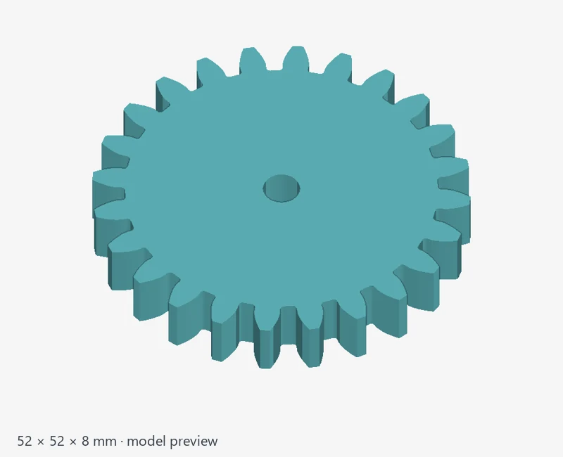
Choose Tooth style = Straight spur, Module = 2, Teeth = 24, Face width = 8 mm, Round bore = 5 mm, Bore allowance = 0, Pressure angle = 20°, Tooth thinning = 0, Mating gear teeth = 0, and all hub fields = 0. Leave Design notes blank. The sample card's Recreate this sample download gives the complete tested steps. Pitch diameter is 48 mm and outside diameter is 52 mm. Changing only the tooth style to Helical or Herringbone with 25° helix gives a 52.962 mm pitch diameter and 56.962 mm outside diameter because the module is now normal-system. Update the 3D preview to see the angled teeth. For a same-size mate with the same angle, use the opposite hand. Print a shaft/tooth fit test before using the gear. A Mating gear teeth value calculates a mate but does not generate one; choose Gearworks for a complete matching set.
If generation rejects a tooth count, bore wall or hub size, correct that combination rather than repeatedly retrying it. Reopen the main Model Studio guide for queue limits, saving and sharing. Select another generator in Model Studio and use Instructions to open its forum post.
HELICAL AND HERRINGBONE — DOWNLOADABLE EXAMPLES
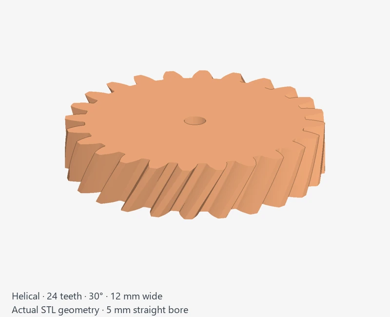
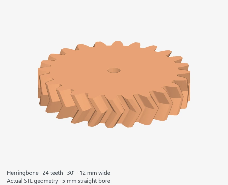
The sample cards below show renders of the exact downloadable STLs. Each includes Download STL, Recreate this sample, Exact settings (JSON), and a complete sample kit with print notes and checksums. The original straight spur sample remains available.
Shared settings for BOTH new examples: Teeth 24; Size by = Normal module (mm), value 2; Face width 12 mm; Helix angle 30°; Normal pressure angle 20°; Round bore 5 mm; Bore allowance 0; Tooth thinning 0; Mating gear teeth 0. Set every top/bottom hub field to 0 and leave Design notes blank. Expected pitch diameter is 55.426 mm and outside diameter is 59.426 mm, with a total height of 12 mm.
HELICAL EXAMPLE: Choose Tooth style = Helical and Helix direction = Right. The teeth slope continuously through the full 12 mm width. Select Update 3D preview, then Generate gear STL.
Download the helical STL.
HERRINGBONE EXAMPLE: Choose Tooth style = Herringbone and Lower-half helix direction = Right. The lower 6 mm follows that hand and the upper 6 mm reverses, creating a continuous chevron without a center gap. Select Update 3D preview, then Generate gear STL.
Download the herringbone STL.
Print either sample flat on an end face with the bore vertical. Both exact downloads passed watertight-solid checks and native Orca slicing with layer/toolpath previews. These are software checks; no physical print or load rating is claimed. Select your own printer and filament and inspect the sliced toolpaths. Zero bore allowance and tooth thinning demonstrate nominal geometry; adjust them after a measured fit test.
To make an equal-size parallel-shaft mate, regenerate the same design with Left hand (opposite lower-half hand for herringbone). Nominal center distance is 55.426 mm. Match module, pressure angle, helix magnitude and face width; align herringbone center planes. Rotate one gear until its teeth enter the other gear’s gaps before engaging them; opposing tooth tips must not be lined up. Turn the pair in opposite directions. The matching opposite-hand 24:24 and 24:36 pairs were checked through a complete tooth cycle using the actual mesh solids and cross-sections, with no detected interference. This is a digital geometry check, not a physical fit or wear test. Helical gears produce axial thrust, so check shaft/bearing support. Mating gear teeth does not generate a second part.
INTERNAL RING GEARS — STRAIGHT, HELICAL AND HERRINGBONE
Choose Gear type = Internal ring gear, then choose the tooth style and size as above. Teeth point inward around an open center. Rim thickness is the radial material OUTSIDE the tooth roots, not the whole wall including the teeth. Shaft bores, splines and hubs are hidden and ignored for rings. Generate creates this ring only; make its external pinion separately, or use Gearworks for a complete matched set.
For normal module mn and helix angle beta (0 for straight spur): pitch diameter = mn × ring teeth / cos(beta); tooth-tip opening = pitch diameter − 2 × mn; root opening = pitch diameter + 2.5 × mn; complete outside diameter = root opening + 2 × rim thickness. Size by Ring outside diameter includes the rim. Changing sizing methods preserves the current valid geometry. Width is the complete ring height.
The base-circle guard requires at least 35 teeth at 20°, 64 teeth at 14.5°, or 23 teeth at 25°. Root-relief and tooth-tip checks can require more teeth; for example, a straight 25° ring with zero thinning needs 48 teeth for this circular root relief. Start with 48 teeth at 20°. Ring limits: 200 teeth, normal module 0.2–10 mm, rim thickness 1–50 mm, complete outside diameter up to 500 mm, width 0.6–100 mm and 300,000 output triangles. Detail is not silently simplified. Tooth thinning reduces the inward teeth and enlarges their gaps; measure a printed fit test before selecting the final allowance.
Mating pinion teeth is optional (0 skips it). It calculates center distance = transverse module × (ring teeth − pinion teeth) / 2 and checks the generated transverse profiles through a tooth cycle. The pinion needs at least 18 teeth at 20°, 32 at 14.5°, or 12 at 25°, and at least 12 fewer teeth than the ring; combinations with detected profile interference are rejected. These limits are conservative and do not implement profile shifts. The check does not rate strength or replace a printed fit test.
An internal ring and its external pinion turn in the SAME direction. Match module and pressure angle. For parallel-shaft helical or herringbone internal meshes, match NORMAL module, NORMAL pressure angle and helix magnitude, with the SAME hand (same lower-half hand and aligned center planes for herringbone). This differs from two external gears, which use opposite hands. Helical rings still create axial thrust. Align the teeth with the mating gaps before engagement.
INTERNAL STARTER: Gear type = Internal ring gear; Tooth style = Straight spur; Size by = Module, value 2; Teeth = 48; Face width = 8 mm; Rim thickness = 4 mm; Pressure angle = 20°; Tooth thinning = 0; Mating pinion teeth = 24. Expected pitch diameter 96 mm, tooth-tip opening 92 mm, root opening 101 mm, outside diameter 109 mm and center distance 24 mm. Make the external pinion with 24 teeth, module 2 and 20° pressure angle. Use a separately measured shaft bore. Changing both parts to Helical or Herringbone at 25° gives ring pitch diameter 105.924 mm, tooth-tip opening 101.924 mm, root opening 110.924 mm, outside diameter 118.924 mm and center distance 26.481 mm. Use the same hand for both parts.
Select Update 3D preview and inspect the inward teeth and continuous rim. Generate gear STL, review the completed solid, then download or send to Slicer Studio or Support Fin Studio. Edit gear design restores the ring type, rim, tooth style, angle, hand and mating pinion count. Existing external gear projects keep their original behavior.
Internal gear reference:
https://khkgears.us/media/beqhhrye/gear-solutions_khk_internal-ring-gears-design-and-considerations.pdf
Helical hand reference:
https://www.eassistant.eu/fileadmin/dokumente/eassistant/etc/HTMLHandbuch/en/ExternalGearHelp.html
WORKSPACE, SAVED PROJECTS AND PREVIEW CONTROLS
Choose a generator under New model project; the Instructions button follows the selected tool. Define your model in the setup card, then follow generation and checks in the build table. Saved projects can be searched by name or tool and filtered by status. Refresh projects updates the list without discarding the setup form.
In a completed project, Fit model, Top, Front and Bottom help inspect every side. Drag to rotate, pinch to zoom, and use two fingers or Shift-drag to pan. Pan view makes a one-finger drag pan the preview. Color, Solid and Wireframe inspect different aspects of a colored result. If the color preview cannot load, the solid STL remains available and Color retries the textured view. Preview cameras and display modes do not change the exported geometry.
Clear / start over resets the current workspace while keeping the selected generator. Saved projects and earlier versions are kept. A Reconnect notice lets you recover after a connection interruption. The page pauses background queue checks and refreshes status when you return.
CHOOSING ONE GEAR OR A COMPLETE PAIR
Use Gear type to choose External teeth or Internal ring gear in this builder. The optional mating tooth count checks/calculates a partner; it does not generate that partner. Use Gearworks for its complete paired mechanisms. Internal helical mates use the SAME hand; two external parallel-shaft helical gears use OPPOSITE hands. Match the normal module, pressure angle, helix magnitude and actual shaft spacing.
RELATED INSTRUCTIONS
Model Studio tool directory ·
Slicer Studio ·
Support Fin Studio ·
Community models ·
Android app setup ·
Report a problem
 P0k3sm0t