Open
Enclosure in Model Studio.
ENCLOSURE — CASES FOR BOARDS, BATTERIES AND COMPONENTS
Spec-sheet AI suggests measurements, mounting points and ports; you review them before the CAD builder creates the case. You can also enter measured dimensions without an image. All geometry controls use millimeters.
QUICK START
1. Open Model Studio → New model project → Enclosure. Enter a Project name and add each Board, battery, or component.
2. Enter component width, depth and complete height, including tall connectors. Optionally upload one clear JPG, PNG or WebP dimension drawing per component and select Read spec sheet. Include top and side views when available. Reading can take several minutes; progress appears in the component panel.
3. Compare suggestions and source evidence with the drawing. Choose Use known dimensions, Add mounting point to review or Add port opening to review only for values you verify. Unknown dimensions stay blank. Measure missing values; AI does not establish exact sizes from an undimensioned photograph. Pin headers are not mounting holes.
4. Choose Style and set wall, floor, lid thickness, Lid fit clearance and Component spacing. Arrange side by side or stacked and select Arrange & fit case to components, or Keep my positions for manual layout. Check the resulting interior dimensions. Recheck port positions whenever arranging changes component positions.
5. Set mounting supports and Ports & wire access as described below.
6. Select Update 3D enclosure preview. Rotate the case and switch Lid view between Exploded, Assembled and Hide lid. Check component guides, numbered openings, posts, vents and clearances. Changing dimensions invalidates the preview; update it again.
7. Tick I checked component dimensions, mounting holes, spacing, and every port/wire opening, then Generate enclosure STL.
8. Inspect the finished result. Download printable STL contains the body and inverted lid laid beside it for printing; Download body & lid ZIP supplies separate STLs, saved dimensions and assembly notes. Print either the layout or individual files, not both. Open top produces the body only. Test fit before installing electronics.
RECREATE THE RASPBERRY PI 4B VENTED SAMPLE
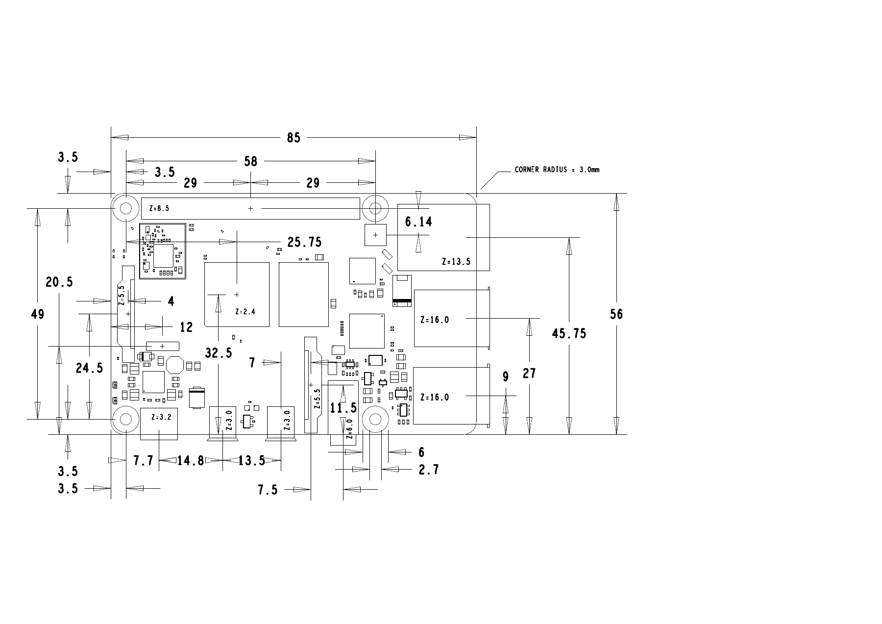
Use the sample card's Full mechanical drawing (PNG), showing the complete uncropped page from Raspberry Pi's official mechanical PDF:
https://pip.raspberrypi.com/documents/RP-008343-DS . A mechanical drawing gives sizes; an electrical schematic does not supply enclosure clearances. The full source PDF is in the kit. This example is for a bare Raspberry Pi 4 Model B, not Pi 5.
Upload the full-page PNG under the component's Spec-sheet image and select Read spec sheet. No manual cropping is required for this example. The improved reader was rerun through the normal browser controls: it found the 85 × 56 mm board, all four mounting centers and seven visible edge-connector positions. Front centers are X=11.2, 26, 39.5 and 54 mm; right centers are Y=9, 27 and 45.75 mm. Coordinates follow the printed dimension chains, not typical-board defaults. Connector types remain unconfirmed. Choose Use known dimensions and Add mounting point to review for each detected hole, then check the values below.
Add port opening to review copies the correct wall and center plus your component X/Y offset. Recognized types now select editable starter openings; unidentified types stay blank until you choose Port type or enter measurements. These defaults are allowances, not dimensions read from the drawing. The prototype below deliberately uses grouped service windows instead of seven close-fitting openings; do not add both sets. Z= labels alone are component extents, not port-center heights. Verify all suggestions, units and the whole drawing before generating. The kit includes the rerun reader report and checked settings.
For this example, use a 20 mm component height envelope, X=3, Y=3, Bottom lift=5 mm. Choose Individual mounting points at board-local (3.5,3.5), (3.5,52.5), (61.5,3.5), (61.5,52.5) mm: a 58 × 49 mm pattern, not four equal corner insets. Use 2 mm screw pilots, then verify/drill for your actual fasteners.
Choose Breathable — vented lid, 2 mm wall/floor/lid, 0.25 mm lid fit clearance and 3 mm spacing. Choose Keep my positions with a 91 × 62 × 35 mm interior. Enable wire entry. Recreate this sample lists all six reviewed rectangles for front power/HDMI/audio, right USB/Ethernet, left microSD, and lid GPIO/camera/display cables. These are generous grouped service windows, not close-fitting individual connector outlines. The 20 mm height, screw pilots, window sizes and case dimensions are deliberate design allowances, not exact AI measurements.
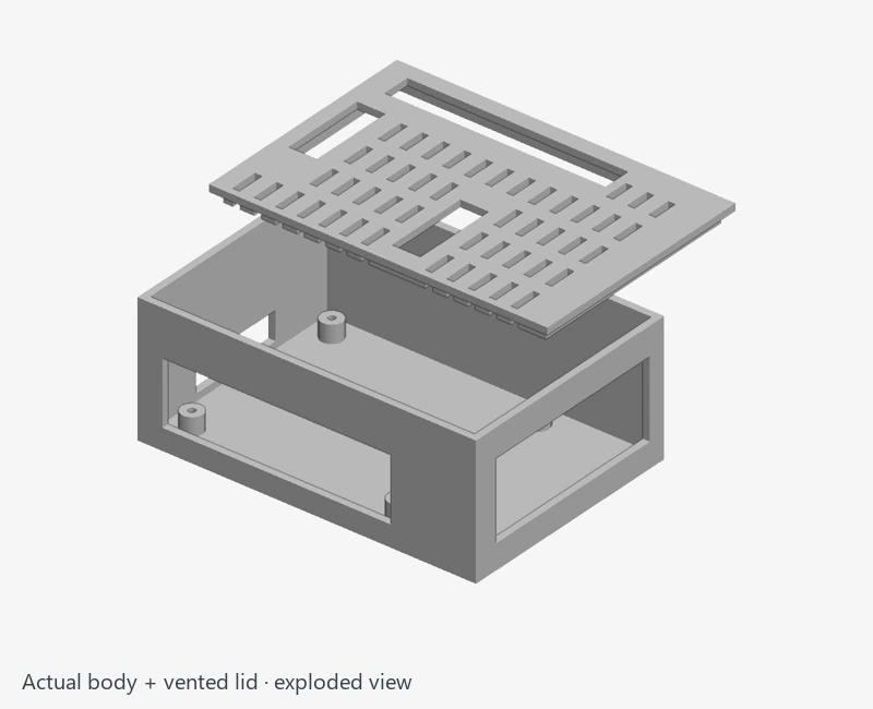
Update the preview, inspect Assembled/Exploded/Hide lid, confirm and generate. Download the 198 × 66 mm combined print layout OR the body/lid files in the kit; individual body footprint is 95 × 66 mm. The preview image shows an exploded view of those same parts. Print body floor-down and lid flat, then flip the lid for assembly. Check actual plug reach, microSD removal, fastener fit, retention and cooling with a prototype. The model passed saved-geometry and native slicing checks; no physical fit or thermal test has been performed, and HAT/heatsink/cooler clearance is not certified.
CHOOSING A STYLE
• Fully enclosed with removable lid: body and a slip-fit locating lid.
• Open top — one open side: body without a lid.
• Breathable — vented lid: body with lid vents.
• Sealed design — gasket channel: requires a suitable gasket, external compression hardware and sealed glands. Selecting this style does not make a printed case certified airtight or waterproof.
MOUNTING AND COMPONENT POSITIONS
Under Position & mounting holes choose No posts, Four corner posts for a measured rectangular pattern, or Individual mounting points for irregular patterns. Enter only actual fixing holes. Individual points use board-local X/Y centers and a screw pilot diameter for each post. A board's clearance-hole diameter is not automatically the right screw pilot size.
Component X/Y position is its front-left corner inside the case; Bottom lift (Z) is above the inside floor. In the top view, front is at the bottom, X goes right and Y goes toward the back. Posts support the bottom lift and must clear walls and other components. Stacked parts need suitable support hardware. Component guide boxes are excluded from the STL.
PORTS AND WIRE HOLES
Choose + Port or wire opening. Set purpose and wall, then choose Port type or enter a custom rectangle/circle. Templates cover USB-C, Micro USB, single/double USB-A, Micro/Mini/full HDMI, Ethernet/RJ45, 3.5 mm audio/AV and DC barrel jacks. Sizes include basic clearance; check actual cable plugs. Nominal center heights assume a 1.6 mm PCB and top-mounted connectors; change Center above board bottom for your hardware. Across (U) starts at the interior left edge on front/back walls, or the front edge on left/right walls. Up (V) starts at the inside floor. For the lid, U = X and V = Y. Under Follow board position choose a board and its local edge/height centers. Imported ports link automatically when their along-edge position is known. U follows board X/Y and V follows Bottom lift plus the connector center. Editing U/V switches to manual placement. Linked openings and edited sizes survive Edit enclosure design. Fit messages flag floor/edge/lid clearance; Arrange & fit includes opening height. Ports never shrink or shift to fit a short case. Nearby openings still need 3D review.
Enable Allow wire entry / cable-gland holes for wire openings. Leave room to insert plugs, bend cables and reach connectors; a visible port alone does not establish its opening size. For a vented case with top wire exits and side power access, choose Breathable, add measured wire openings on the Lid over both sides of the board, and a Port access opening on the correct side wall. Do not add USB access if only power should be accessible.
Sealed designs allow round cable-gland holes only and require confirmation that you will fit and seal the glands. A hole alone is not airtight. Follow manufacturer cooling, electrical and battery enclosure requirements.
REVIEW, SAVE AND REVISE
If the preview rejects overlapping posts, insufficient walls or invalid openings, correct the indicated field. Notes are descriptive; geometry follows numerical controls. Edit enclosure design reloads saved settings into a new project while preserving earlier files. Spec-sheet images stay private; finished STL files and saved dimensions are retained. Enclosures initially stay private for fit review and follow the AI-generated free-only sharing rule. The main Model Studio instructions cover queues, limits and storage.
WORKSPACE, SAVED PROJECTS AND PREVIEW CONTROLS
Choose a generator under New model project; the Instructions button follows the selected tool. Define your model in the setup card, then follow generation and checks in the build table. Saved projects can be searched by name or tool and filtered by status. Refresh projects updates the list without discarding the setup form.
In a completed project, Fit model, Top, Front and Bottom help inspect every side. Drag to rotate, pinch to zoom, and use two fingers or Shift-drag to pan. Pan view makes a one-finger drag pan the preview. Color, Solid and Wireframe inspect different aspects of a colored result. If the color preview cannot load, the solid STL remains available and Color retries the textured view. Preview cameras and display modes do not change the exported geometry.
Clear / start over resets the current workspace while keeping the selected generator. Saved projects and earlier versions are kept. A Reconnect notice lets you recover after a connection interruption. The page pauses background queue checks and refreshes status when you return.
FULL DRAWINGS AND PORT TEMPLATES
The reader can analyze a complete dimension drawing with multiple views; cropping is optional when a page is hard to read. Review every suggested mounting point and connector. Known port types offer editable basic opening templates, not guaranteed measurements of your board or plug. Follow board position links an opening to the component placement and lift; compare its wall, center, height and cable clearance in the actual 3D preview.
RELATED INSTRUCTIONS
Model Studio tool directory ·
Slicer Studio ·
Support Fin Studio ·
Community models ·
Android app setup ·
Report a problem
 P0k3sm0t