
 P0k3sm0t
SEE WHAT THE TOOL MAKES
Try a studio sample
These previews show the actual downloadable models. They are geometry renders, not photographs of physical prints. Each kit includes print notes; choose your own printer and filament before slicing.
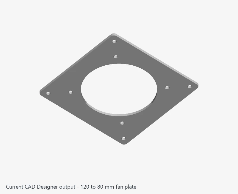
120 to 80 mm fan adapter
120 × 120 × 3 mm plate, 80 mm opening, 4.5 mm holes on 105 and 71.5 mm mounting squares.
About this sample
Refreshed from the included reviewed feature specification with the current CAD Designer builder on October 27, 2026. Use Recreate this sample for the form settings. Print flat and check both mounting patterns before use. This is a flat adapter plate.
Open CAD Designer in Model Studio.
CAD DESIGNER — DESCRIPTION TO REVIEWED MECHANICAL CAD
Describe what the part must do and the dimensions you know. Local language-model AI proposes a feature plan; trusted CAD code builds the solid and holes. The description is used to plan geometry, rather than only becoming listing text. AI cannot guarantee that it understood every detail, so compare the proposed features with your request.
QUICK START
1. Open Model Studio → New model project → CAD Designer. Enter a project name and description.
2. Include outside sizes, thickness, hole diameters, mounting-hole center spacing and positions where known. For a flat fan adapter, say “plate”; a tapered duct is a different part. All design controls use millimeters.
3. Select Analyze description. The local AI can take a few minutes. Planning is queued separately from STL generation; keep the page open for the result. Only one analysis per visitor/account runs or waits at a time. There are up to four pending analyses globally and ten analysis requests per hour per visitor/account.
4. Read Requested features, Assumptions to check, and any questions. Missing functional measurements or unsupported requests block generation. Update the description with answers and analyze again. Reference defaults are proposals, not verified dimensions for your hardware.
5. Expand each feature to review or edit its sizes and center position. The origin is the center of the main body in X/Y, with Z=0 at the bottom. Added solids are joined first, then openings are cut. A four-hole pattern uses hole-CENTER spacing, not outside plate size. Through-all round holes extend through the entire body along their axis.
6. Select Update 3D preview. This is the actual CAD geometry that will be generated. Drag to rotate, pinch/scroll to zoom, and inspect both sides, every hole and the overall dimensions. A missed or duplicate cut, disconnected body or invalid dimension needs correction.
7. Check the review confirmation and select Generate reviewed CAD STL. Changing the description or measurements invalidates that confirmation and preview. Preview approvals expire after 15 minutes or a server restart; update the preview again if asked. STL generation uses the normal shared worker queue and generation allowance.
8. Open the saved project to download its STL or Send to Slicer Studio. Edit CAD design restores the saved feature plan; preview it again before generating a new project. Original versions are preserved. Normal AI Library sharing and printability checks still apply.
EXAMPLE: A FLAT 120 MM TO 80 MM FAN ADAPTER
Use the full tested description below to recreate the downloadable sample. The site's reference design is a 120 × 120 × 3 mm plate, with 4 mm rounded XY corners, a centered 80 mm round airflow opening, four 4.5 mm mounting holes at 105 × 105 mm centers and four at 71.5 × 71.5 mm centers. The reference comes from the site's earlier adapter design. Those sizes must appear as assumptions when you have not explicitly supplied them. Measure your actual fans and fasteners; nominal fan size alone does not establish mounting spacing or clearance. You can state your own values in the description instead.
RECREATE THE DOWNLOADABLE FAN-ADAPTER SAMPLE
Enter this complete description:
Make a 120 x 120 x 3 mm rounded plate with XY corner radius 4 mm and center X=0, Y=0, Z=1.5. Cut a centered 80 mm diameter through airflow hole. Cut four 4.5 mm through holes in a 105 x 105 mm centered mounting pattern and four 4.5 mm through holes in a 71.5 x 71.5 mm centered mounting pattern. Both mounting patterns have center X=0, Y=0. One connected flat plate, bottom Z=0.
Analyze it, then review the four features: one added plate, one round airflow cut and two four-hole patterns. Check the dimensions above; AI planning can vary, so expand and correct a numerical field if necessary. Update the 3D preview, verify nine through openings in total, confirm the review checkbox and generate the STL. The sample card also provides Recreate this sample with these steps. The included design JSON is a numerical reference, not a file the website imports.
WHAT THIS VERSION CAN MAKE
One connected mechanical part assembled from axis-aligned boxes/rounded plates and cylinders, with box pockets, round holes and four-hole patterns. This covers many simple plates, spacers, rings, brackets and mounts. Features are bounded to 48 per design, with a maximum 400 mm outside size; check your selected printer's build volume separately. Added solid dimensions and round-hole diameters start at 0.8 mm. Multiple components, arbitrary organic surfaces, lofted ducts, angled boxes, threads, text and gear teeth are not supported by this designer. Use Enclosure, Spur Gear Builder or Gearworks for their supported specialized designs, or external CAD for other geometry.
CHECKS AND LIMITS
Each requested cut must actually remove material. The result must be one closed, consistently oriented solid. The server rebuilds the reviewed design independently and compares the complete submitted solid, including openings, before accepting the STL. These checks establish geometry consistency; they do not establish load rating, minimum wall thickness everywhere, printer tolerance or hardware fit. Inspect sliced layers, supports, remaining material around holes and a test print before using the part.
PRIVACY AND RECOVERY
Planning runs on the server's local AI service. The browser does not contact that service directly, and no generated scripts are executed. Planning results are private to your visitor session/account and expire 15 minutes after completion; a server restart clears unfinished planning results. Saved CAD projects retain their descriptions and feature plans. If analysis fails or needs details, no replacement shape is silently generated. Refine the request and try again.
WORKSPACE, SAVED PROJECTS AND PREVIEW CONTROLS
Choose a generator under New model project; the Instructions button follows the selected tool. Define your model in the setup card, then follow generation and checks in the build table. Saved projects can be searched by name or tool and filtered by status. Refresh projects updates the list without discarding the setup form.
In a completed project, Fit model, Top, Front and Bottom help inspect every side. Drag to rotate, pinch to zoom, and use two fingers or Shift-drag to pan. Pan view makes a one-finger drag pan the preview. Color, Solid and Wireframe inspect different aspects of a colored result. If the color preview cannot load, the solid STL remains available and Color retries the textured view. Preview cameras and display modes do not change the exported geometry.
Clear / start over resets the current workspace while keeping the selected generator. Saved projects and earlier versions are kept. A Reconnect notice lets you recover after a connection interruption. The page pauses background queue checks and refreshes status when you return.
CHOOSING A TOOL FOR AN EXISTING FILE
CAD Designer plans a new mechanical solid from a description and reviewed dimensions. To change an uploaded mesh, use MeshRight for mesh edits or Mesh to CAD for STEP/FreeCAD conversion. Gear teeth belong in Spur Gear Builder or Gearworks; words, QR codes and hardware pockets belong in Sign & keychain. These tools do not recover missing measurements from an image.
RELATED INSTRUCTIONS
Model Studio tool directory · Slicer Studio · Support Fin Studio · Community models · Android app setup · Report a problem