MESH TO CAD: EDIT A PRINTABLE MESH IN FREECAD, SOLIDWORKS OR ANOTHER CAD TOOL
Need to edit a printable mesh in CAD?
Open the STL to STEP Converter to review repair options and export checked STEP or FreeCAD solids. Original sketches and feature history are not recovered.
Open Model Studio and choose Mesh to CAD. Upload an STL, OBJ, 3MF, PLY or OFF file, select its source units and choose Convert to editable CAD. The server checks and converts the file through the model queue; follow progress in your build table. Your uploaded file and converted project stay private.
1. Choose the file and check its units. Give the project a name if desired.
2. Keep Merge flat faces and Recognize round surfaces enabled. For complex curved parts, optionally enable Fit freeform surfaces (Beta). Use optional simplification only when needed.
3. Select Convert to editable CAD and wait for the queued job to finish.
4. Inspect the preview and conversion report, then download STEP or FreeCAD.
The primary output is STEP: real closed boundary-representation solid bodies with selectable CAD faces, rather than an STL wrapped in another extension. Merge flat faces joins coplanar triangles into larger faces. The native FreeCAD document contains Part Design bodies. Complete cylindrical walls, round holes, bosses, tubes, rounded extrusion profiles and full spheres can become analytic CAD surfaces within the selected deviation limit. Unrecognized or rejected regions retain their CAD faces, which can remain faceted. Original sketches and feature history are not recovered. STEP exchanges solid geometry; editable features depend on your CAD software.
FILES TO DOWNLOAD
• STEP: import into FreeCAD, SolidWorks or another CAD application that supports STEP solids. Use this for exchanging editable CAD geometry.
• FreeCAD: open the native FCStd document and work from its Part Design bodies.
• OpenSCAD: a self-contained polyhedron with scale controls. Combine it with your own shapes and boolean operations. It is mesh-derived code, not recovered parametric CAD or a SolidWorks format.
• Complete CAD kit: all three files, conversion report, README and checksums.
• Printable STL: the converted mesh used for the on-page preview. Material/color information is omitted from CAD conversion.
EDITING IN FREECAD
Open model.FCStd, expand a Solid body and select its final feature. Select a suitable planar face, add a sketch, constrain the new sketch, then use a supported Part Design operation such as Pad or Pocket. You can also use Part booleans to add a boss or cut a hole. Recognized spheres receive an editable Sphere radius. Suitable simple extruded profiles receive a fitted sketch, circle-diameter/arc-radius constraints and editable Pad depth. These are inferred features, not the original design history. For other models, add your own features to Converted base solid. STEP does not carry this FreeCAD feature tree. Save your edited native project, then export a fresh STEP/STL if needed.
FREECAD SPEED TIP: REFINE
On a dense spline model, select your new Pocket in the model tree, open its Data properties and set Refine to false if recomputing is slow. Refine cleans up residual edges after the operation; disabling it avoids automatic face merging. It does not simplify the uploaded mesh or replace spline surfaces with flat facets. Recompute, inspect the solid and save under a new filename. This is a FreeCAD feature property, separate from Model Studio's Merge flat faces and optional simplification settings. See
FreeCAD Pocket properties.
The edited curved examples in this post already have Pocket Refine disabled. Their full edit/check sequences completed in about 38 seconds in FreeCAD 1.0.2; actual speed depends on your machine and edit. If there is no suitable planar face on a curved part, create the sketch on an XY/XZ/YZ base plane or a datum plane and position it using Placement. Each example's Recreate & edit download gives the exact plane, placement, circle diameter and Pocket length used in its test.
EDITING IN SOLIDWORKS OR OTHER CAD SOFTWARE
Open/import the STEP file using your application's solid-import option. Confirm it imports as solid bodies and check units and dimensions. Use the application's import diagnostics if needed, then create new sketches, extrudes, cuts, holes or direct edits on those bodies. Available feature-recognition tools depend on your application and license; Model Studio does not promise a recovered native feature tree. Use STEP rather than the FCStd or SCAD file in SolidWorks.
TESTED EXAMPLES: BRACKET, CURVED LOOP AND SCULPTED KNOB
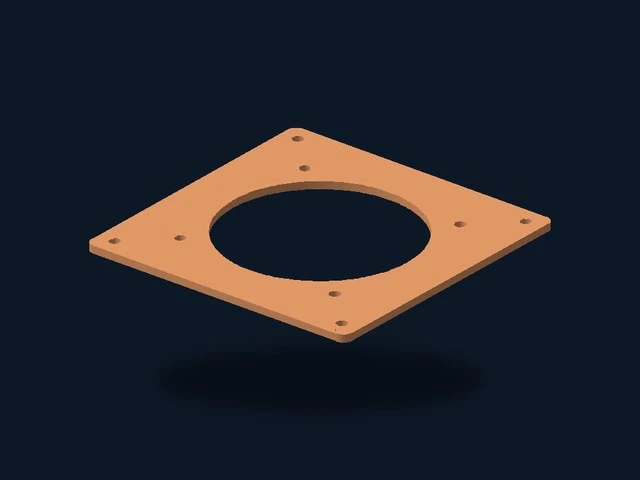
The sample cards at the top of this post include images rendered from the actual converted geometry, named downloads and repeatable conversion/editing instructions. Each new kit contains the original STL, converted STEP/FreeCAD/OpenSCAD files, a printable converted STL, edited STEP and FreeCAD examples, settings references, test results and SHA-256 checksums. The existing smooth fan-plate sample is also available.
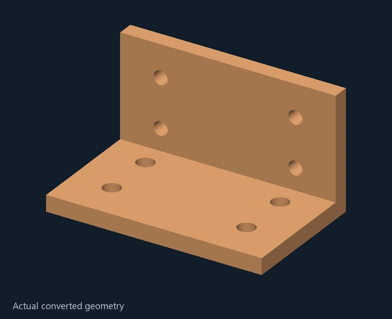
• Eight-hole mounting bracket: 6,204 input triangles became 16 CAD faces — eight planes and eight true cylindrical hole walls. All four 6.4 mm base holes and four 5.2 mm upright holes retained their centers and axes. The edited example enlarges one base hole to 9 mm. Keep Recognize round surfaces ON and Fit freeform surfaces OFF.
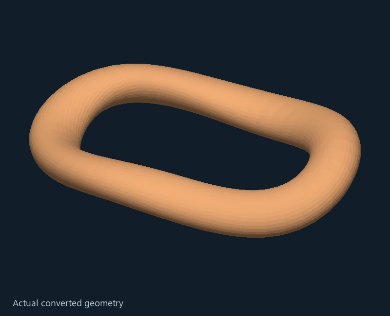
• Twisted curved loop: all 3,456 input triangles became 3,456 B-spline CAD faces; its central opening remained open. The edited example adds a 2.5 mm hole through the loop. Enable Recognize round surfaces and Fit freeform surfaces.
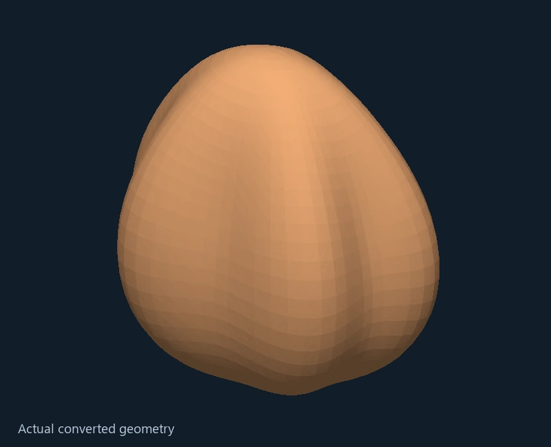
• Sculpted curved knob: all 3,600 input triangles became 3,600 B-spline CAD faces. The edited example adds a 4 mm axial hole. Enable Recognize round surfaces and Fit freeform surfaces.
For all three, use Millimeters, sewing tolerance 0.01 mm, maximum surface deviation 0.05 mm and optional simplification OFF. These inputs were converted without mesh simplification. The bracket's lower CAD face count comes from recognizing surfaces and merging coplanar faces, not decimating its source mesh. The 4,000-triangle freeform limit does not apply to its round-surface-only conversion; the general 20,000-triangle preparation limit still applies.
In FreeCAD 1.0.2, all three converted STEP files opened as valid closed solids. We added real sketch/Pocket edits, changed their dimensions, saved/reopened the edited STEP and FreeCAD files, then changed sketch diameter and Pocket depth again in the saved native examples. Curved-model deviation stayed within 0.05 mm; spline seams are not guaranteed tangent-continuous. The detailed curved conversions took about four minutes each on the test server, so allow the queue to finish. These are software-verified geometry examples, not physical print, fit or load tests; SolidWorks was not directly tested.
To try the existing edit immediately, open edited.FCStd from a kit and change EditableHoleSketch or EditablePocket. To recreate the conversion, upload input.stl and follow recipe.txt. settings-reference.json records values for manual entry; it is not an importable saved website project. Use either input.stl or converted.stl when slicing, not both on top of each other.
AUTOMATIC REPAIR AND PRINTABLE EXPORT CHECKS
Repair small mesh defects is ON by default. It removes duplicate/degenerate triangles, corrects inconsistent winding, orients separate outer bodies while preserving enclosed cavities, stitches existing open-edge vertices within the sewing tolerance (up to 0.01 mm), makes collinear T-junction seam edges conform without capping a surface, and closes simple convex, nearly flat triangle/quad gaps up to 1 mm across. Hole filling is additionally limited by surface area. It does not voxelize the model, close large openings, guess missing shapes or automatically union intersecting bodies. Your original upload remains unchanged; conversion.json records actions, before/after topology, small gaps filled and maximum vertex movement. Disable the repair checkbox if you want defects to stop conversion instead.
STEP/FreeCAD geometry and the printable STL/OpenSCAD preview are checked together before export. Round-surface Boolean joins now use a small checked tolerance to avoid microscopic seams. If a fitted surface still cannot produce a closed matching printable preview, conversion retains the checked original CAD surfaces and records a warning; that region can remain faceted. The fallback never substitutes an unrelated shape or relaxes the final watertight/volume checks.
INPUTS AND OPTIONS
STL/OBJ/PLY/OFF files normally carry no reliable physical units, so choose millimeters or inches explicitly. 3MF uses its stored physical units and transforms. All exports use millimeters. Multiple separate closed parts remain separate solid bodies, in their original placement, up to 16 closed shells per conversion. Nested inner shells are kept as cavities when the CAD kernel can validate them. Overlapping bodies are rejected with guidance to Boolean-union them in an editor or convert them separately. Self-intersections, zero-volume surfaces and damage beyond the bounded repairs can still fail.
The upload limit is 90 MB. CAD conversion accepts up to 20,000 triangles after preparation; CAD faces are substantially more expensive than a slicer mesh. For dense models, enable optional simplification and choose 3,000, 6,000 or 12,000 triangles. Simplification is an approximation that can remove fine detail and change dimensions. A conversion that changes volume by more than 2% during simplification is rejected. Preserving the mesh does not silently simplify it.
SURFACE FITTING AND ACCURACY
Recognize round surfaces fits complete cylindrical walls, circular arcs on extruded profiles and full spherical shells. It checks ring geometry, curvature, orientation and the maximum distance from the prepared mesh before using an analytic surface. Coarse intentional polygons are not turned into circles. Partial spheres, intersecting features and ambiguous shapes may remain faceted.
Fit freeform surfaces (Beta) builds cubic Bezier/B-spline patches for other closed curved shapes, up to 4,000 triangles per shell. It retains sharp edges and bounds displacement over each entire patch, then checks the sewn solid, bounds and volume. These are real editable CAD surfaces, not display smoothing. There can be many patches, and tangent continuity across their seams is not guaranteed; complex shapes may still need manual surface cleanup. Recognized analytic solids take priority over the freeform replacement. Nested cavities or failed surface fits retain the original CAD faces, and the report lists skipped fits. This is not a universal reconstruction of a designer's intended surfaces or constraints.
Maximum surface deviation defaults to 0.05 mm, adjustable from 0.0001 to 0.25 mm. It applies to fitted surfaces relative to the prepared mesh, not an unknown original CAD model. Optional simplification is a separate approximation. Smaller tolerances accept fewer analytic surfaces and reduce freeform smoothing. Inspect dimensions, seams, thin walls and retained openings before manufacturing. The report shows the fitted surfaces, maximum deviation, CAD face counts, inferred native parameters and any skipped fits. For freeform fits, displayed dimensions follow the checked native printable tessellation; its resolution is recorded in the report. The deviation bound applies to the entire CAD surface itself.
Sewing tolerance defaults to 0.01 mm and joins CAD edges. It is separate from fitting tolerance and does not fill missing surfaces. Use a smaller sewing tolerance for small details. Printable STL and OpenSCAD exports tessellate the final checked CAD geometry; only STEP and FreeCAD retain smooth CAD surfaces.
PROCESSING TIME AND MEMORY
Detailed freeform fits can take several minutes. The CAD worker monitors memory and stops a conversion if its observed native-process memory exceeds 2 GiB. The time limit is four minutes, extended to five minutes for freeform inputs above 3,000 triangles. A stopped job does not silently simplify your model. The conversion report records preparation time, native processing time and observed peak memory.
IF CONVERSION FAILS
Keep Repair small mesh defects enabled and retry a failed conversion while its private source is retained. Larger missing surfaces and non-manifold intersections still need a trusted mesh/CAD editor. Errors now list open/non-manifold edge counts and report triangle-budget problems together. A high triangle count needs explicit simplification or external mesh reduction; repair does not raise the 20,000-triangle conversion limit. In testing, repair closed a 225,706-triangle Benchy's duplicate/seam defects, but all three automatic simplification budgets still produced invalid topology, so the conversion was correctly stopped. Such a model needs topology-preserving reduction in an editor rather than repeated retries. If the private source has expired under normal retention, upload it in a new project. Queued/running conversions can be cancelled. Check the conversion report, dimensions, retained holes and cavities before using the result.
Documentation:
FreeCAD mesh import workflow,
FreeCAD shape from mesh.
WHEN TO USE MESHRIGHT FIRST
Keep Repair small mesh defects enabled for bounded automatic cleanup. If the report still shows open boundaries, intersections or invalid topology, inspect and repair the input in MeshRight, export a new STL, and retry Mesh to CAD. Repair is separate from simplification and does not raise the conversion budget. Preserve the original and compare holes, cavities and dimensions after any repair.
RELATED INSTRUCTIONS
Model Studio tool directory ·
Slicer Studio ·
Support Fin Studio ·
Community models ·
Android app setup ·
Report a problem
 P0k3sm0t