
 P0k3sm0t
SEE WHAT THE TOOL MAKES
Try a studio sample
These previews show the actual downloadable models. They are geometry renders, not photographs of physical prints. Each kit includes print notes; choose your own printer and filament before slicing.
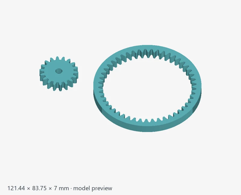
Ring gear and pinion
Module 1.5, 18/48 teeth, 7 mm face width, 22.5 mm shaft center distance.
About this sample
Verified through the normal Gearworks form and saved STL download. Use Recreate this sample for the exact tested steps and settings. Generated by Gearworks, with both parts in print orientation. Individual STLs and the generator specification are included. Assemble using the shaft spacing in generation-report.json. Check tooth engagement and fit with a physical prototype. This sample has no rated torque or wear life.
Open Gearworks in Model Studio.
GEARWORKS — ADVANCED GEAR BUILDER
Choose Gearworks under New model project for matching two-component mechanisms. Spur Gear Builder creates one external gear or one internal ring with straight, helical or herringbone teeth. External gears can have toothed hubs and custom shaft splines; internal rings use adjustable outer rims. Choose Gearworks when you want the complete two-part set and assembled preview, rather than one ring or gear.
Available sets:
• Internal ring & pinion: an external pinion inside a larger ring, on parallel shafts. The ring must have at least 12 more teeth than the pinion.
• Bevel ring & pinion: a straight bevel pair for intersecting 90-degree shafts. This is not automotive hypoid gearing or a certified vehicle replacement.
• Worm drive: a cylindrical worm and a throated wheel generated for the specified worm pitch diameter and number of starts. Shafts cross at 90 degrees. Reduction = wheel teeth / starts; wheel thickness follows from throat coverage. Do not assume the printed drive will self-lock.
• Helical pair: matching opposite-handed gears for parallel shafts. Plan for shaft thrust.
• Herringbone pair: mirrored helical halves on each gear.
• Rack & pinion: rotary-to-linear motion. Rack length = rack teeth × π × module; travel per pinion revolution = pinion teeth × π × module.
1. Choose the set. Enter module, tooth counts and face width; bevel face width is measured along the pitch cone. Shared module and pressure angle preserve the mating tooth sizes. Gear diameters cannot be set independently of module and tooth count.
2. Enter each available shaft bore. Zero leaves a solid center. Bore allowance adds to nonzero hole diameters only. Tooth thinning is separate and reduces each part's teeth. Set ring backing, helix angle, worm dimensions/starts/throat coverage or rack backing as applicable.
3. Select Preview gear set. The CPU CAD engine creates actual geometry and checks sampled tooth engagement. Drag to rotate, zoom, and switch between Assembled and Print layout. The orange/blue preview colors identify components and do not assign filament colors. Any dimensional edit makes the preview stale; update it before generating.
4. Select Generate gear set STL. Inspect the validated result. Download either the combined print-layout STL or Download gear set ZIP, which contains both individual STLs, a combined layout, the numerical design, dimensions/assembly transforms and the geometry-library notice. Print the combined layout OR the individual files, not both. Send to Slicer Studio for orientation, supports and print settings. Edit Gearworks design reloads saved numerical fields into a new project.
Limits include module 0.5–4 mm, up to 100 pinion teeth / 120 driven teeth, 300 mm gear envelopes, 400 mm rack length, face width 2–30 mm, and four worm starts. Additional undercut, shaft-wall, bevel cone-width, lead-angle, interference and complexity limits apply. Previews are explicitly requested, bounded to one active build, and may take several seconds. Invalid combinations are rejected; reduce complexity or adjust dimensions before retrying.
These are printable prototypes, not rated gear products. Sampled engagement checks are not a strength or lifetime certification. Test shaft fit, backlash, support removal, tooth contact and operating loads. Finished pairs stay private for review and use the existing free-only AI sharing rules. Geometry uses a pinned BOSL2 library with CPU Manifold construction: https://github.com/BelfrySCAD/BOSL2
STARTER EXAMPLE
Choose Internal ring & pinion, 18 pinion teeth, 48 ring teeth, Module 1.5 mm, Face width 7 mm, Pressure angle 20 degrees, Ring backing 4 mm, Tooth thinning per part 0.1 mm, Pinion bore 5 mm and Bore allowance 0.2 mm (a 5.2 mm final bore). These are the downloadable sample's settings; the initial form uses 8 mm width, so change it to 7. Leave Project notes blank, then select Preview gear set. The sample card's Recreate this sample download provides every step. Inspect Assembled to understand engagement and Print layout to see the two printable parts. Enter your actual shaft measurements and preview again before generating.
WHEN A PREVIEW FAILS
Read the indicated dimensional or engagement error. Ring counts need at least a 12-tooth difference; overly large bores, thin walls or incompatible tooth combinations must be changed. Wait for an active preview to finish rather than repeatedly requesting it. If a dimensional field changes, select Preview gear set again to enable generation. Sampled engagement is not a guarantee of printed fit. To read another generator's instructions, select it in Model Studio and use Instructions. The main Model Studio forum post covers queues, limits and sharing.
WORKSPACE, SAVED PROJECTS AND PREVIEW CONTROLS
Choose a generator under New model project; the Instructions button follows the selected tool. Define your model in the setup card, then follow generation and checks in the build table. Saved projects can be searched by name or tool and filtered by status. Refresh projects updates the list without discarding the setup form.
In a completed project, Fit model, Top, Front and Bottom help inspect every side. Drag to rotate, pinch to zoom, and use two fingers or Shift-drag to pan. Pan view makes a one-finger drag pan the preview. Color, Solid and Wireframe inspect different aspects of a colored result. If the color preview cannot load, the solid STL remains available and Color retries the textured view. Preview cameras and display modes do not change the exported geometry.
Clear / start over resets the current workspace while keeping the selected generator. Saved projects and earlier versions are kept. A Reconnect notice lets you recover after a connection interruption. The page pauses background queue checks and refreshes status when you return.
PRINT LAYOUT AND ONE-GEAR ALTERNATIVE
Generate the complete set here when both mating parts are needed. The combined STL is a separated print layout, not the assembled mechanism. Individual ZIP components and their assembly transforms describe the same set. For a single external gear or internal ring, including helical or herringbone rings with your own pinion, choose Spur Gear Builder instead.
RELATED INSTRUCTIONS
Model Studio tool directory · Slicer Studio · Support Fin Studio · Community models · Android app setup · Report a problem